Blog
Battleship Kentucky, AEGIS Conversion
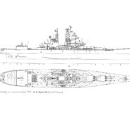
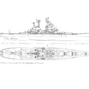
This is my final version of the USS Kentucky, depicted as a modern Guided Missile Battleship. I decided to go back to the the well as it was for this one. I was never quite happy with how any of the 1995 versions of this ship turned out. So, I finally went (literally) back to the drawing board. This time I added AEGIS to control the ship’s AAW missiles. I also decided to completely replace the stacks with ones that made it more clear that the ship now has Gas Turbines instead of Steam Turbines. I also decided to add a proper enclosed hanger for the ship’s helicopters along with storage sheds for the ship’s Pioneer Reconnaissance Drones. The ship would now use Mk41 VLS launchers for all AAW, ASW, & ASuW missiles (except for the Harpoon Missiles which would still use deck mounted quad cannister launchers). Finally, I decided to restore the ship’s original hull number. While she’d still be classified as a Guided Missile Battleship (BBG), she’d revert back to using the regular battleship hull number sequence. At the time of her recommissioning, she (along with her sister, the Illinois) would be the largest, most powerful, and somewhat ironically, the most technologically advanced Surface Combatant in the World.
As for the ship itself, there was a ‘real’ battleship Kentucky. It was never completed and eventually scrapped while still half built. There were proposals to make her a guided missile ship, but obviously they were never acted on. This drawing represents my vision of how she could have appeared in the Nineties with AEGIS and VLS as a unit of a notional Illinois Class (named after her aforementioned sister ship that also wasn’t completed). While she has essentially the same dimensions as an Iowa class Battleship (both she and the Illinois were to be units of that class) there are enough differences for her and her sister to be considered a completely different class.
Overall, the armor of this ship (and her sister, the Illinois) would differ in many ways from an Iowa class battleship. The hill would also be a bit different as well. Since this ship is part of an “alternate timeline” concept, I figured “why not go all the way”? I decided to go all the way to when this ship was still on the drawing board and starting altering things right from the start. Obviously, I could only change details of the design, but those details can make quite a difference. The Illinois and Kentucky were actually a redesign of the Iowa class anyways so making additional changes wouldn’t be unreasonable. The structural design of the torpedo protection system was revised and the overall structural design was revised so the ships could be of entirely welded construction as opposed to a combination of riveted and welded construction. I decided to go even further than that with both the hull design and details of the armor protection. I somewhat reshaped the hull forward, streamlining it a bit to eliminate the hard shoulder the Iowas have just forward of their Number 1 Gun Turrets. I’m hoping this would help both seakeeping and hydrodynamic efficiency.
The armor would be an evolution of the Missouri’s and Wisconsin’s (which had their forward armor bulkheads and the fronts of the forward barbettes thickened) armor scheme. The main armor deck would see the most significant changes. It would go from 4.75” on a 1.25” backing plate (with 5” on 1.25” above the torpedo protection system), to 5” on a 1” backing plate (with 5.3” on 1” above the torpedo protection system). The turret faceplates would go from 17” on a 2.5” backplate, to 18” on a 1.5” backplate. The conning tower and the sides of the barbettes would be thickened by 0.2” from 17.3” to 17.5”. As a weight compensation, the turret and conning tower roofs would be reduced in thickness by 0.5”, from 7.25” to 6.75”. I always felt the armor on the roofs of the conning tower and the turrets was excessive, especially in comparison to the rest of the armored citadel. Reducing them to be more in line with the outboard sections of the decks bought the weight needed to beef up the conning tower and barbettes. I also felt the backing plates for the main armor deck were excessively thick and by thinning them, I could thicken the plates above them with no increase in weight.
In addition to replacing the Mk10 Terrier Missile launcher with a Mk41 VLS launcher, the 5” Secondary Battery has been replaced as well. The twin 5”/38cal Mk28 mounts have been replaced by modern single Mk45 5”/54cal mounts. Now these are a bit different than other Mk45s in that they feature 2.5” HY80 gun shields in place of the normal 1/2” thick ones. For this reason they’re designated as the Mk45mod2(b). As the thicker gun shield is really the only difference from other Mk45mod2 guns, a separate model designation is unwarranted and thus just receive a “(b)” sub-designation (plus I just didn’t want to mess around with the designations of the Mk45 variants and create confusion there).
The deckhouse structure attached to the aft superstructure replaces the Number 3 Turret. It is heavily armored to largely simulate the weight of the removed turret and barbette. It would have originally served a Mk10 Terrier Missile Launcher when the ship was originally completed. The Mk10 launcher has been landed along with the structure it sat upon and the roof of the deckhouse removed with the installation of what amounts to a tandem merged Mk41 launcher. This launcher has 122 cells for missiles, with 6 more cells taken up by replenishment cranes.
As suggested by the new stacks, the Steam Turbines (and their associated Boilers) along with the Steam Turbo-Generators have been completely replaced here. She would now use Gas Turbines for both propulsion and electrical power generation. Due to the new propulsion and power systems weighing far less than the previous systems, significant changes would be made in the Engineering spaces. The new engines would have heavily reinforced and insulated foundations to reduce vibration, noise, and protect the engines from shock damage. This ship would be nearly as quiet as a Spruance or Arleigh Burke at cruising speeds.
The innermost bottom structure of the ship would also be heavily reinforced with an additional layer of steel plate with a layer of sound insulation atop that and then yet another layer of steel. The holding bulkheads of the side protection system would also be heavily reinforced along with all of the transverse bulkheads in the Engineering spaces. These measures would serve two purposes. The first would be to improve the ship’s longitudinal strength allowing it to better withstand underbottom explosions. The second, would be to add over 1,500 tons of additional structure to compensate for how much lighter the ship’s new propulsion and electrical plant is.
The fire controls would also be updated with most of their analog components replaced with solid state digital computers. The fire control radars themselves would be similarly upgraded, with the Mk13 radar on the Main Battery Director (Mk38) being replaced with a new, all digital PESA AN/SPQ-13 radar (Which is basically the one fictitious component of the ship. It is essentially an enlarged and somewhat modified AN/APQ-164 radar from a B-1B Lancer) . The Secondary Battery Directors (Mk37s) on the other hand would be replaced outright by somewhat newer Directors (Mk68s) mounting AN/SPG-53F radars. However, only the fore and aft directors would be replaced, with the two waist Directors eliminated. All of these systems would be integrated into two Mk 34 Gun Weapon Systems (GWS), with one supporting the 16” (406mm) guns, and the other supporting the 5” (127mm) guns. These systems would allow for data linking with other platforms to obtain telemetry for plotting firing solutions (as well as providing telemetry and targeting data for friendly ships and aircraft).
All of these combat systems would be controlled from a large CIC that would be located in former engineering spaces. This ship would also be extensively outfitted and equipped to serve as a Fleet Flagship. It would be equipped with a Tactical Flag Command Center (TFCC), along with Intelligence and Communication spaces that would allow this ship to serve quite effectively in this role. Some of these spaces would also occupy engineering spaces freed up by the conversion to Gas Turbines. Finally, I should note that the Conning Tower depicted here is the three-story Force Flagship version.
Specifications (for 1995 recommissioning):
Length: Waterline: 860′ (262.13meters), Overall: 887′ (270.35meters)
Beam: 108’2″ (32.97meters)
Draft: 35’5” (10.8meters) [not including sonar dome]
Displacement: (full load) 55,800 tons
Power Plant:
Propulsion: 8x General Electric LM2500 Gas Turbines (26,250 bhp each; 210,000 bhp total), coupled to 4 Shafts, driving either 5-bladed (inner shafts) or 4-bladed (outer shafts) reversible controllable-pitch propellers
Electrical: 6x Rolls-Royce AG9140 AC Gas Turbine Generators (3,000 kW, 450V each; 18,000 kW total), 2x 400-cycle 2,000 kW Emergency Diesel Generators
Maximum Speed: 32.5 knots
Crew Complement: 1,020 Officers and Enlisted Personnel (Standard), 1,050-1,080 Officers and Enlisted Personnel (when serving as a Flagship/Command ship)
Armament:
6 (2×3) Mk7 16″ (406mm) 50cal guns
6 (6×1) Mk45mod2(b) 5″ (127mm) 54cal guns
3 MK 41 VLS Launchers (1×122 + 2×61) with a standard loadout of: 112 SM-2 (RIM-66M) Standard Missiles, 20 RUM-139 ASROC ASW Missiles, 112 BGM-109 Tomahawk Cruise Missiles
6 (6×4) Mk141 launchers (24 RGM-84 Harpoon Missiles)
2 (triple tube) Mk32 torpedo launchers (each launcher holds 3 Mk46mod5 NEARTIP torpedoes)
6 (6×1) Mk15 Vulcan Phalanx 20mm CIWS
4 (4×1) .50cal machine guns
4 (4×1) 7.62mm machine guns
Sensors:
Sonar: AN/SQQ-89 ASW Combat System (AN/SQS-53C Bow Sonar, AN/SQR-19 Towed Sonar, & AN/SQQ-28 LAMPS III Shipboard System)
Air Search: AN/SPY-1D PESA 3D S-Band Radars, AN/SPS-49(v)5 L-Band radar, AN/SPN-43 S-Band Air Traffic Radar
Surface Search: SPS-67(v)3 C-Band Radar, AN/SPS-64(v)9 X-Band Navigation Radar
Fire Control/Targeting: AN/SPQ-13 (replaces Mk13) X-Band Radar, 6 (6×1) AN/SPG-62 I-J-Band Radars, 2 (2×1) AN/SPG-53F X-Band Radars, Mk23 TAS, 2 (2×1) Mk46 Optical Sight Systems, Mk38mod5 Gunfire Director, 2 (2×1) Mk68 Gunfire Directors
Electronic Warfare and Countermeasures:
AN/SLQ-32(v)3 Electronic Warfare Suite
AN/SLQ-25A Nixie Acoustic Torpedo Decoy System
Mk36mod8 SRBOC Chaff System
Aircraft:
4 SH-60B Seahawk Helicopters (housed in two tandem hangars)
2 RQ-2 Pioneer Reconnaissance UAVs (housed in two sheds atop the Hanger)
F-24A ‘Ghost Hawk’ Stealth Fighter
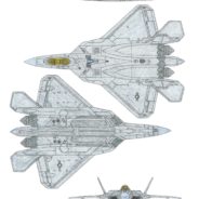
So, here’s my first drawing of 2018. It certainly took far longer than I anticipated with having to rework numerous elements as it progressed and even starting over completely at one point. So, a month behind schedule it’s finally done. Like my previous drawing, it’s more of a design rendition than anything else. Unlike my previous drawing, this one is a mostly original design as opposed to a modification of an existing design. I call it the ‘F-24A Ghost Hawk’. The name itself is something of an oblique reference to the YF-23, as one of the two prototypes was named the ‘Grey Ghost’. It incorporates design elements from the YF-23, F-22, Su-57, & F-35 as well as some of my own ideas and concepts.
The plane (in the fictional AU it resides in) would be jointly developed with Mitsubishi Heavy Industries drawing on some of the experience from the ATD-X/ Shinshin X-2 project. Most of the technology for this plane already exists and it would use “off the shelf” components extensively (with a lot of avionics being shared with the F-35 Lightning II and the F/A-18 Super Hornet). About the only exception would be the AN/APG-84 radar. Even this wouldn’t really be an example of new technology as it’s basically an AN/APG-81 with a larger antenna and different track-and-scan abilities (It can track 48 aerial targets simultaneously and attack 16 of them, or attack up to 4 surface targets at once. The APG-81 can track 23 aerial targets and attack 19 of them, or attack 1 surface target). This radar is slaved to a rear facing AN/APG-83(v2) that allows the F-24 to turn away from an enemy target while continuing to guide a missile towards it. My next drawing project will most definitely be more expressive and far less technical. For anyone who wants to know, the F-24’s specs would be as follows:
Northrop Grumman/Boeing/Mitsubishi F-24A Ghost Hawk
General characteristics
– Crew: 1 (pilot)
– Length: 65ft 7in (20m)
– Wingspan: 45ft 10in (13.95m)
– Height: 15ft 6in (4.72m)
– Wing area: 876 ft2 (81.4 m2)
– Empty weight: 39,400 lb (17,875 kg)
– Loaded weight: 67,200 lb (30,485 kg) Air-to-air mission configuration
– Max. takeoff weight: 87,000 lb ( 39,645 kg)
– Fuel capacity: 24,000 lb (10,886 kg)
– Powerplant: 2 x Pratt & Whitney F119-PW-120 afterburning turbofans with thrust vectoring in pitch-axis
– Dry thrust: 26,400 lbf (117.4 kN) each
– Thrust with afterburner: 38,400 lbf (170.8 kN) each
Performance
– Maximum speed:
– At altitude: Mach 2.25+ (1,485+ mph, 2,395+ km/h)
– Supercruise: Mach 1.9 (1,254 mph, 2,020 km/h)
– Range: 1,700 nmi (1,955 mi, 3,150 km) on internal fuel
– Combat radius: 820 nmi internal air-to-air configuration (943 mi, 1519 km), 685 nmi (with 100 nmi in supercruise) (788 mi, 1,269 km)
– Ferry range: 2,260 nmi ( 2,600 mi, 4,190 km) with 2 external fuel tanks
– Service ceiling: >65,000 ft (>19,800 m)
– Rate of climb: >55,000 ft/min (>280 m/s)
– Maximum g-load: +9 g
Armament
– Guns: 1x 30mm (1.18in) GIAT 30/M791 autocannon with 210 rounds
– Hardpoints: 4 x underwing hardpoints (2 wet) with a capacity of 18,000 lb (8,160 kg), 2 x fuselage equipment hardpoints (which can alternatively each mount a Sidewinder missile), 6x internal bays with a capacity of up to 9,800 lb ( 4,445 kg); total payload capacity is 23,000 lb ( 10,430 kg) with provision to carry combinations of:
– Missiles:
– Air-to-air missiles:
– AIM-120D AMRAAM
– AIM-9X Sidewinder
– AIM-132 ASRAAM
– AIM-152C ALRAAM
(Typical A2A loadout 8x AIM-120D, 2x AIM-9X)
– Air-to-surface missiles:
– AGM-88 AAGM
– AGM-158 JASSM
– AGM-65 Maverick
– Brimstone missile / MBDA SPEAR 2
– SPEAR 3
– Joint Air-to-Ground Missile (JAGM)
– SLAM-ER
– Anti-ship missiles:
– AGM-84 Harpoon
– Joint Strike Missile (JSM)
– Long Range Anti-Ship Missile (LRASM)
– Bombs:
– Mark 82, 83, or 84 GP bombs
– Mk.20 Rockeye II cluster bomb
– Wind Corrected Munitions Dispenser (WCWD) capable
– Paveway series laser-guided bombs
– Small Diameter Bomb (SDB)
– Joint Direct Attack Munition (JDAM) series
– AGM-154 JSOW
Avionics
– AN/APG-84 AESA radar (forward facing)
– AN/APG-83(v2) AESA radar (rear facing, slaved to the AN/APG-84)
– AN/AAQ-37 (v2) Distributed Aperture System (DAS)
– AN/ALR-94 radar warning receiver (RWR) 250 nmi (287 mi, 463 km) or more detection range
– AN/AAR-56 Missile Launch Detector (MLD)
– AN/AAQ-40 E/O Targeting System (EOTS)
– BAE Systems Digital Electronic Warfare System (DEWS)
– Northrop Grumman AN/ASQ-242 CNI system
– Helmet-Mounted Display System (HMDS)
F-15M Stealth Eagle
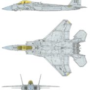
Just completed my first drawing in over a year. My artistic muscles are definitely a bit flabby, but I think I turned out a decent drawing. Granted it’s more a design rendition than what might truly be considered art. I call it the F-15M Stealth Eagle and it is an evolution of Boeing’s Silent Eagle concept. Changes include making it a single seat fighter instead of a two-seater and adding more stealth features. I also enlarged the control surfaces, as well as reshaping the wingtips, tail, and the conformal fuel tanks which also contain multiple internal weapons bays. While still not a true all-aspect stealth fighter, it’s pretty close. It would definitely outclass the Su-57 and at least match the J-20 for stealth. Between that, it’s sensor capabilities, sensor fusion (not anywhere near as good as an F-35’s, but still better than any 4th gen Fighter), and supercruise ability, it would certainly qualify as a 5th Generation fighter.
Basically, all of the technology I put into this notional design already exists. Two exceptions would be the AN/AAQ-42 MAS and the F115-PW-200 engines which don’t actually exist. These two things don’t represent any new technologies though. The AN/AAQ-42 is basically a hybrid of the AN/AAQ-37 DAS and the AN/AAQ-32 IRST with 3 sensors arranged in a single scanning axis. Likewise, the AN/ASQ-239(v2) used by this plane is essentially the same EW system used by the F-35, but has a few features (like the ALE-70 towed decoy) omitted and has been modified to work within the F-15 airframe. The F-115 engines are basically shortened and thus less powerful versions of the F-119 engines used on the F-22 Raptor.
There would also be a naval variant that would look nearly identical externally, designated the F-15N Sea Eagle (and a two-seat F-15O Ocean Eagle). That’s one of the reasons for the larger wings and flaps as well as the higher empty weight versus previous (and real) Eagle versions. This is basically my vision of what the F-15X could have been. There would also be export variants with four other countries using some version of this plane. Some would look almost identical to the American versions, while others would differ quite a bit visually depending on the needs, priorities, and budget of the client nation. For those that want to know, it’s specifications would be as follows:
Boeing F-15M Stealth Eagle
General characteristics
-Crew: 1 (pilot)
-Length: 63.5 ft (19.35m)
-Wingspan: 42.8 ft (13.05m)
-Height: 16.25 ft (4.95m)
-Wing area: 680 ft2 (63.1m2)
-Empty weight: 33,000 lb (14,970kg)
-Loaded weight: 58,800 lb internal air-to-air configuration (26,670kg)
-Max. takeoff weight: 81,000 lb (36,700kg)
-Powerplant: 2 x Pratt & Whitney F115-PW-200 afterburning turbofans with thrust vectoring in pitch and roll axes
-Dry thrust: 23,250 lbf (103.3kN) each
-Thrust with afterburner: 33,900 lbf (150.6kN) each
Performance
-Maximum speed: Mach 2+ (1,320+ mph, 2,128+ km/h)
-Supercruise: Mach 1.55+ (1023+ mph, 1,646+ km/h)
-Rate of climb: 55,000+ ft/min (279+ m/s)
-Service ceiling: 60,000 ft (18,200 m)
-Combat radius: 700 nmi clean (805 mi, 1,295 km); 570 (with 100 nmi in supercruise) clean (655 mi, 1,055 km)
-Ferry Range: 2,100 nmi (2,415 mi, 3,885 km) with 3 external drop tanks
Maximum g-load: +9 g
Armament
-Guns: 1x 20 mm (0.787in) M61A2 Vulcan 6-barreled Gatling cannon with 500 rounds
-Hardpoints: 8x internal hardpoints in four conformal weapons bays and two ventral weapons bays, with a combined maximum capacity of 5,000 lb (2,265 kg), typical A2A loadout being 6x AIM-120D AMRAAM AA missiles & 2x AIM-9X Sidewinder AA missiles, 5x external hardpoints (4 underwing, 1 central fuselage) with a maximum capacity of 20,500 lb (9,300kg) of ordnance, pods, and/or external fuel tanks, total carrying capacity is 23,000 lb (10,400kg)
Avionics
-AN/APG-82(v2) active electronically scanned array (AESA) radar
-AN/AAQ-42 Electro-Optical MAS (Multi Aperture System; composed of 3 separate infrared sensors; 1 facing forward, 1 facing left, & 1 facing right with a continuous 330 degree arc of sensor coverage in the x-axis)
-AN/AAQ-40 Electro-Optic Targeting System (EOTS)
-AN/AAR-56 Missile Launch Detector (MLD)
-Joint Helmet Mounted Cueing System (JHMCS)
-BAE Systems AN/ASQ-239(v2) ‘Barracuda’ Electronic Warfare System
-Digital “Fly-by-Wire” Flight Control System (DFCS)
-Link-16 fighter data link
The Starship Alliance
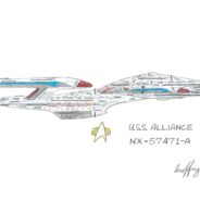
This is a re-do, or maybe even a re-boot of my previous drawing of the Alliance. Conceptually, it is the same as the previous version, however it was approached a bit differently. For starters, this new one was done on regular paper as opposed to notebook paper, it also has somewhat more up to date design language as well as more weaponry. The ship design was conceived of as a Starfleet counterweight to all of the super-warships the Federation kept encountering.
It is a full fledged battleship with a massive arsenal of weaponry and formidable defenses. Commissioned in 2385, almost a decade after the end of the Dominion War, she would succeed the Enterprise as the Flagship of the Federation. For the geeks out there, I’m sure the registry number stands out. There is a history behind this ship’s predecessor that I may in some future forum elaborate on.
Specs:
Length: 900 meters
Height: 44 decks
Crew Compliment: Peacetime 1650; Wartime up to 9700
Support Craft: Peacetime: 32 Shuttles of various types, 20 Fighters, and the Captain’s Yacht; Wartime: 12 Shuttles of various types, 80 Fighters, 6 Assault Transports, and the Captain’s Yacht
Maximum Speed: Warp 9.9 (for up to 16 hours); Warp 9.6 (for up to 36 hours); Warp 9 (for up to 100 hours); Warp 8 (for pretty much for as long as fuel holds out)
Defenses: Multi-phasic regenerative shields; Deployable nano-molecular armor (seen in ST:VOY Endgame); Ablative hull armor; she also has extensive stealth systems and design features
Armament: 30 Type-X phaser arrays (33 in separated flight mode); 12 Torpedo launchers ( Each launcher can fire a salvo of up to 5 torpedoes and can fire photon, quantum, or transphasic torpedoes. They can also launch Tri-Cobalt missiles and launch probes.) Total magazine capacity: 2000 torpedoes, missiles, and probes
Mallory, the Late Queen
My beloved Mallory, one of the best dogs I have ever owned or will ever own. May she reign for all eternity.
RIP 1999-2012
Eye Of The Beholder
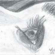
My first drawing of any kind in over two years. I’ve always found a person’s eyes fascinating and felt that doing a drawing that focused exclusively on the human eye as the subject a good way to get back into drawing.
The Battleship Kentucky: A Past Prologue
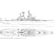
This is something of a prequel to my other drawing of the USS Kentucky. In fact it is actually a major reworking of that drawing that also includes a number of elements of the base drawing by A.D. Baker III worked back into it. My drawing of the Kentucky was in poor material condition when I unearthed it and required a lot of restoration before I could post it here. That involved cleaning up the image and even separately redrawing some parts and then pasting them onto the image. Like I said, it needed a LOT of restoration because it had deteriorated so much in a poor storage environment.
I had always wanted to do a 1960 version of the ship and realized that I could actually use the techniques I had developed and used to repair and restore the drawing to create such a prequel version. It has taken about a month to do it and I am quite pleased with the end result. Correctly scaling the separately drawn elements like the radars so I could scan and then paste them into the drawing was frustratingly difficult and took a lot of trial and error. In some ways this project was harder than the drawing I did from 2009-2012 that led to this project and certainly harder than most of the freehand figure drawings I have done.
As for the fictitious history of this (mostly) fictional ship, I figure due to strains on the US Navy’s manpower resources and budget around 1960, this ship would have essentially been commissioned right into the reserve fleet. It would then remain there until about 1991 or so when it would be activated and rebuilt for service in the 1990s and beyond.
Specifications (when completed in 1960) would be:
Length (WL): 860′
Beam (max): 108’2″
Draft (max): 35’10”
Displacement (full load): 57,000 tons
Power Plant:
Propulsion: 4-Shaft Geared Turbines (53,000shp each; 212,000shp total)
Electrical: 8x 1250 kW Ship Service Turbogenerators, 2x 400-cycle 1,000 kW Diesel Generators (12,000 kW total with no emergency generators)
Maximum Speed: 32knots
Crew Complement: 1,720 Officers and Enlisted Personnel
Armament:
6 (2×3) Mk7 16″ 50cal guns
16 (8×2) Mk12 5″ 38cal guns in 8-Mk28 twin mounts
12 (6×2) Mk22 3″ 50cal guns in 6-Mk33 twin mounts
1 (twin arm) Mk10 missile launcher (holds 80 RIM-2 Terrier surface-to-air missiles on 4-20 round missile rings)
4 (4×1) .50cal machine guns
4 (4×1) 7.62mm machine guns
Search Sensors:
Sonar: The ship as completed would not be equipped with sonar
Air Search: SPS-39 S-Band radar, SPS-37 L-Band radar, SPS-30 height finding radar
Surface Search: SPS-10 C-Band radar
Aircraft:
Provision for the DASH remote ASW helicopter as well as other period helicopters is made in this design. Like the 1995 version, it could probably carry up to 4 helicopters at one time (but there’s no hangar to store any of them).
Battleship USS Kentucky
This is my depiction of the USS Kentucky BBG-2, a Guided Missile Battleship. I started this drawing back in 2009, but didn’t actually end up completing it until 2012 and then let it sit in a folder for 2 years. After such neglect, it was in pretty bad material condition. With a LOT of work, I was able to restore it and even tweak it a bit. I used a drawing by A.D. Baker III of the New Jersey as a starting point and completely reworked it. Unlike much of my other work, this is purely a line drawing. It also is purely a modification of an existing drawing as opposed to a wholly original work. The point of this drawing was less artistic than visually expressing a design I’d come up with. Still, I really like the way this turned out and while the drawing is not a completely original work for me, the design it depicts largely is.
As for the ship itself, there was a ‘real’ battleship Kentucky. It was never completed and eventually scrapped while still half built. There were proposals to make her a guided missile ship, but obviously they were never acted on. My vision of how she could have been completed has her as a unit of a notional Illinois Class (another sister ship that also wasn’t completed), with essentially the same dimensions as an Iowa class Battleship (both she and the Illinois were to be units of that class). The hull is somewhat reshaped forward and the Number 3 Gun Turret has been replaced by a heavily armored deckhouse aft that serves the Mk 10 Missile Launcher. It should be noted that the armor envelope would be a bit different from the Iowa class. In particular, the thickening of the forward armored bulkhead and forward barbettes that the Missouri and Wisconsin received would be eliminated and the Turret and Conning Tower roofs would be thinned by .5″. In addition, the armor distribution for the main armor deck would be redone with a 5″ thick layer on top of a 1″ backing structure instead of the 4.75″ on top of a 1.25″ backing structure.
Although not apparent, the Steam Turbines (and their associated Boilers) along with the Steam Turbo-Generators have been completely replaced here. She would now have a Combined Diesel or Gas (CODOG) arrangement for propulsion and Gas Turbines for generating electricity. Due to the new propulsion and power systems weighing far less than the previous systems, significant changes would be made in the Engineering spaces. The new engines would have heavily reinforced and insulated foundations to reduce vibration, noise, and protect the engines from shock damage. This ship would be nearly as quiet as a Spruance or Arleigh Burke at cruising speeds.
The innermost bottom structure of the ship would also be heavily reinforced with an additional layer of steel plating on top of a layer of sound insulation. The holding bulkheads of the side protection system would also be heavily reinforced along with all of the transverse bulkheads in the Engineering spaces. There would also be new (and quite thick) longitudinal bulkheads running the length of the Engineering spaces. These measures would all serve two purposes. The first would be to improve the ship’s longitudinal strength allowing it to far better withstand underbottom explosions. The second would be to add over 2,500 tons of additional structure to compensate for how much lighter the ship’s new propulsion and power systems are.
Also not shown is the Tactical Flag Command Center (TFCC) this ship would have, along with Intelligence and Communication spaces that would allow this ship to serve quite effectively as a Fleet Flagship. The fire controls would also be updated with most of their analog components replaced with solid state digital computers. The fire control radars themselves would be similarly upgraded, with the Mk13 radar on the Main Battery Director (Mk38) becoming a fully digital radar. The Mk25 radars on the Secondary Battery Directors (Mk37s) on the other hand would be replaced outright by SPG-53s. All of these systems would be integrated into two Mk 34 Gun Weapon Systems (GWS), with one supporting the 16” (406mm) guns, and the other supporting the 5” (127mm) guns. These sytems would allow for data linking with other platforms to obtain telemetry for plotting firing solutions as well as improving the accuracy of plotted firing solutions. Also, the aft Main Battery Plot would be reconfigured into a Combat Information Center (CIC). It should also be noted that the Conning Tower depicted here is the three-story Force Flagship version. Finally, I also reworked the aft stack into a sort of Mack (mast-stack combination) of my own design. More recently, I have superseded this drawing with a revamped and redesigned version.
Specifications (for 1995 recommissioning) would be:
Length (WL): 860′
Beam (max): 108’2″
Draft (max): 35’10” (not including sonar dome)
Displacement (full load): 57,000 tons
Power Plant:
Propulsion: CODOG; 8x General Electric LM2500 Gas Turbines (26,250 bhp each; 210,000 bhp total), 4x Caterpillar 16-cylinder Diesel Engines (20,000 bhp each; 80,000 bhp total), coupled to 4 Shafts, driving either 5-bladed (inner shafts) or 4-bladed (outer shafts) reversible controllable-pitch propellers
Electrical: 8x Allison AG9140 AC Gas Turbine Generators (2,500 kW, 440V each; 20,000 kW total), 2x 400-cycle 2,000 kW Emergency Diesel Generators
Max Speed: 25 knots (Diesel propulsion), 33 knots (Gas Turbine propulsion)
Crew Complement: 1,420 Officers and Enlisted Personnel
Armament:
6 (2×3) Mk7 16″ (406mm) 50cal guns
6 (6×1) Mk45 5″ (127mm) 54cal guns
74 (4×4 ABLs + 2×29 Mk41) BGM-109 Tomahawk cruise missiles
16 (4×4 Mk141) RGM-84 Harpoon missiles
1 (twin arm) Mk10 missile launcher (holds 80 RIM-67B SM-2ER missiles + 20 RUR-5 ASROC anti-sub missiles on 5-20 round missile rings)
2 (triple tube) Mk32 torpedo launchers (each launcher holds 3 Mk46mod5 NEARTIP torpedoes with no reloads)
6 (6×1) Mk15 Vulcan Phalanx 20mm CIWS
4 (4×1) .50cal machine guns
4 (4×1) 7.62mm machine guns
Search Sensors:
Sonar: SQS-53C Bow sonar, SQR-19 Towed sonar array
Air Search: SPS-48E S-Band radar, SPS-49(v)5 L-Band radar
Surface Search: SPS-67(v)3 C-Band radar
Aircraft:
4 SH-60B Seahawk helicopters
Elsa in Pencil
My first drawing of 2014. Actually, it is my first drawing in over 11 months. Queen Elsa from ‘Frozen’ because my of its popularity I thought “why not?” Figured it would be a good subject to get back into drawing with.
(‘Elsa’ and ‘Frozen’ are properties of Disney, all rights reserved and no infringement is intended.)
Treaty Battleship
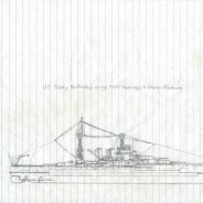
Drawing I did back in 1999 of what I figured a Washington Treaty compliant US Battleship would have looked like using the technology and construction practices available in the 1920s. This is the oldest drawing that I still have. All of my prior work in both ship drawings and figure drawing has since been lost.



Recent Comments